Netskope IPSec with Fortinet FortiGate
This guide illustrates how to configure a VPN IPSec tunnel between Netskope and a FortiGate firewall device. This configuration example uses a FortiGate device running FortiOS version 6.4.3. It can work for all FortiOS versions.
There’re two options to accomplish the configuration: CLI and GUI. The CLI is faster.
FortiGate CLI Configuration
Create a VPN for IPsec Phase 1.
config vpn ipsec phase1-interface
    edit "NSKP-POP-XXXXX"
        set interface "wan1"             << change for your wan interface
        set ike-version 2
        set keylife 28800
        set peertype any
        set net-device disable
        set mode-cfg disable
        set proposal aes128-sha256 aes256-sha256 aes128-sha1 aes256-sha1
        set localid "XXXXX@XXXXXX"       << change for your localid
        set dhgrp 16 15 14
        set remote-gw 163.116.XXXX.38    << change for your selected POP
        set psksecret XXXXXXX            << change for your preshared
    next
end
Create a VPN for IPsec Phase 2.
config vpn ipsec phase2-interface
    edit "NSKP-POP-XXXXX"
        set phase1name "NSKP-POP-XXXXX"
        set proposal aes256gcm aes128gcm aes128-sha1 aes256-sha1
        set dhgrp 16 15 14
        set auto-negotiate enable
        set keylifeseconds 7200
    next
end
Create at least one policy with VPN interface associated.
config firewall policy
    edit 999
        set srcintf "internal"
        set dstintf "NSKP-POP-XXXXX"
        set srcaddr "all"
        set dstaddr "all"
        set action accept
        set schedule "always
        set service "HTTP" "HTTPS"
        set logtraffic all
        set nat enable
    next
end
Create a route to push VPN into RIB.
config router static
    edit 999
        set priority 10
        set device "NSKP-POP-XXXXX"
    next
end
Create a policy-based router to redirect web traffic to Netskope.
config router policy
    edit 998
        set input-device "internal"                 << incoming interface
        set src "172.16.100.0/255.255.255.0"        << LAN network
        set dst "0.0.0.0/0.0.0.0"
        set protocol 6
        set start-port 443
        set end-port 443
        set output-device "NSKP-POP-XXXXX"
    next
    edit 999
        set input-device "internal"                 << incoming interface
        set src "172.16.100.0/255.255.255.0"        << LAN network
        set dst "0.0.0.0/0.0.0.0"
        set protocol 6
        set start-port 80
        set end-port 80
        set output-device "NSKP-POP-XXXXX"
end
FortiGate GUI Configuration
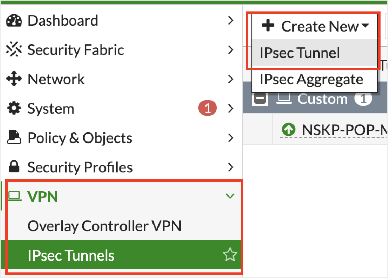
Click + Create New and then IPsec Tunnel.
Under VPN Setup:
Name: Enter a name for the tunnel.
Template type: Select Custom.

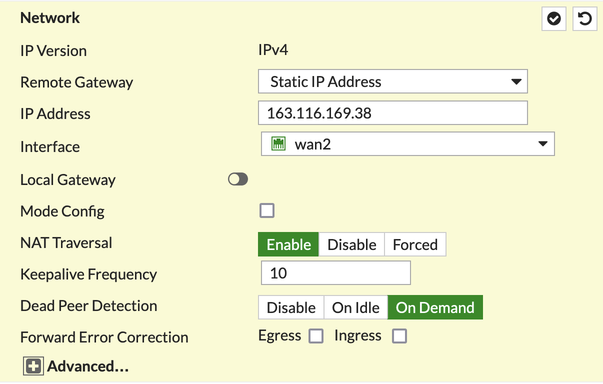
In the Network section, configure the IP address and interface information:
In the Authentication section, configure the pre-shared key and select IKEv2:

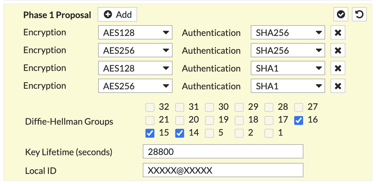
In the Phase 1 Proposal section, configure the following:
Note
The Local ID must be entered.Netskope recommends usingan email format as a local ID, such as xxxx@xxxx.xxx. It must be the same as the source identity in your Netskope tenant.
In the Phase 2 Proposal section, configure the following:
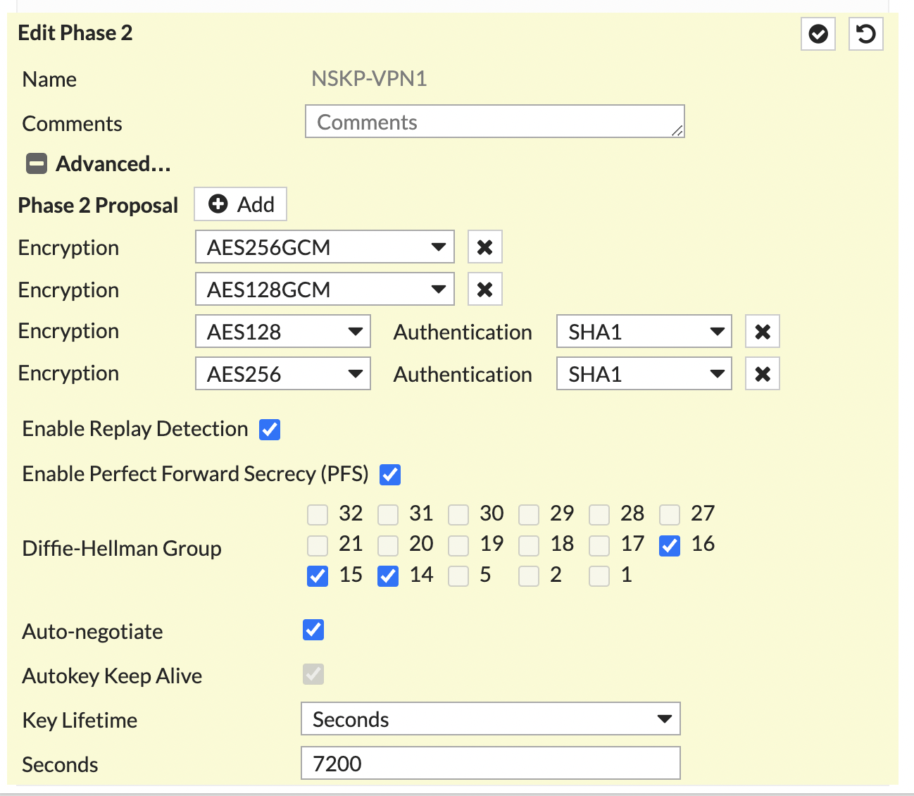
Click OK.
To create at least one policy with a VPN interface associated:
Go to Policy & Objects > Firewall Policy.
Click + Create New.
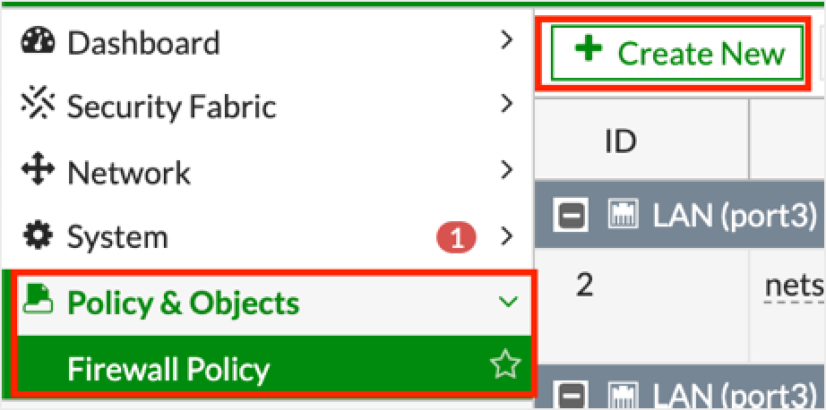
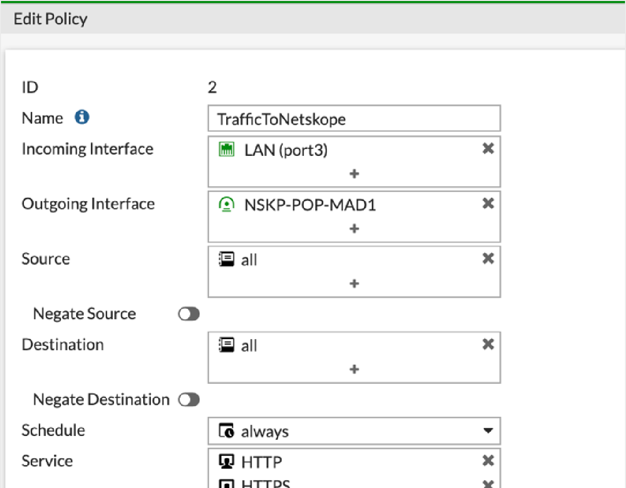
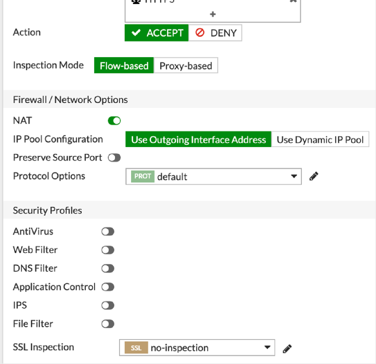
In the Edit Policy window, configure the following fields:
To create a route that pushes the VPN into RIB:
Go to Network > Static Routes.
Click + Create New and then OK.
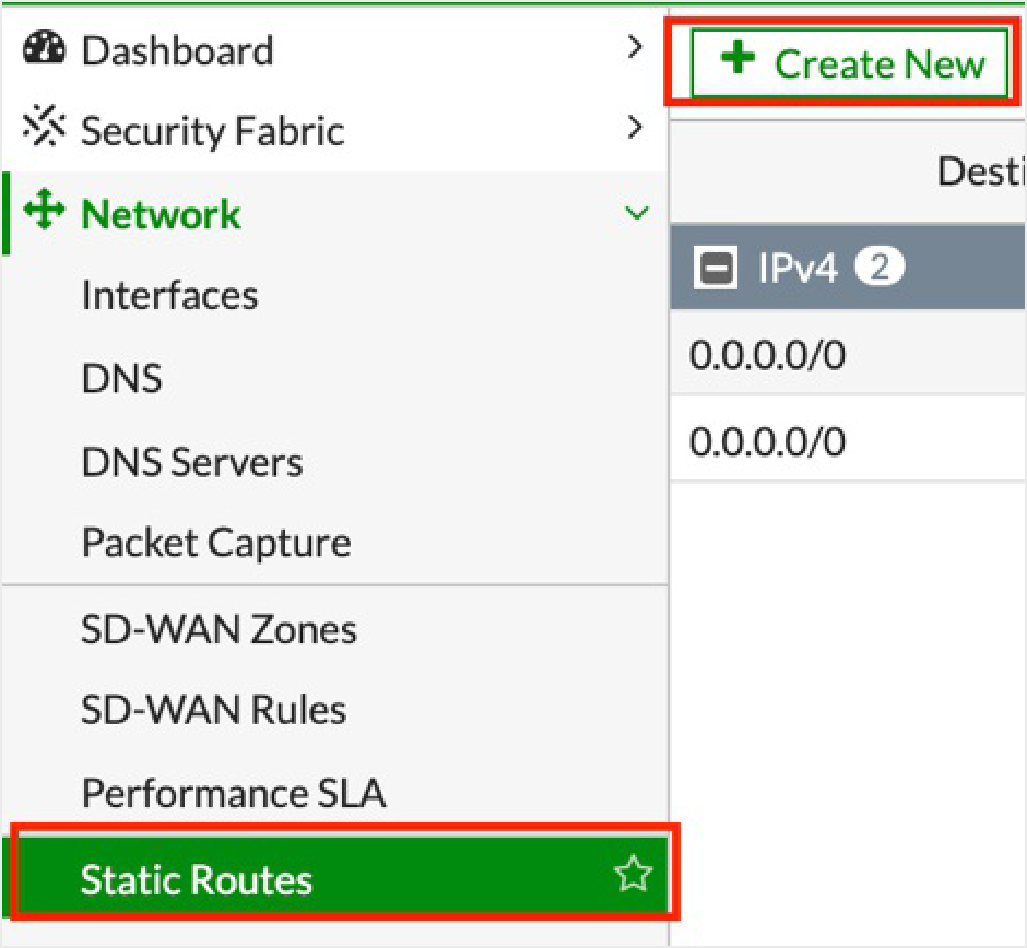
Ensure the Administrative Distance is the same as the original default route but with a higher Priority. For example:
config router static
     edit 3
        set distance 5
        set priority 10
        set device "NSKP-POP-XXXXX"
    next
end
To learn more about Administrative Distance and Priority: Fortinet documentation.
Enter the following commands and ensure there are two static routes installed:
get router info routing-table static
Routing table for VRF=0
S*      0.0.0.0/0 [5/0] via 192.168.1.1, wan1
                  [5/0] is directly connected, NSKP-POP-Milan, [10/0]
If both routes aren't displaying, your original default route might be obtained through DHCP. In the CLI, edit the original default route and
set dynamic-gateway enable, and add values for the following:config router static edit 2 set distance 5 set priority 5 set device "wan1" set dynamic-gateway enable next edit 3 set distance 5 set priority 10 set device "NSKP-POP-XXXXX" next endVerify your two static routes.
By default, policy-based routing (PBR) isn't enabled in the FortiGate GUI, so you must implement a policy-based router to redirect traffic to the Netskope proxy.
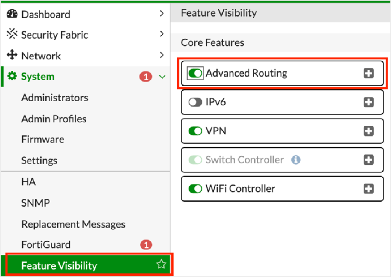
Go to System > Feature Visibility.
Under Core Features, enable Advanced Routing and click Apply. You don't need to reboot. This change doesn’t affect production.
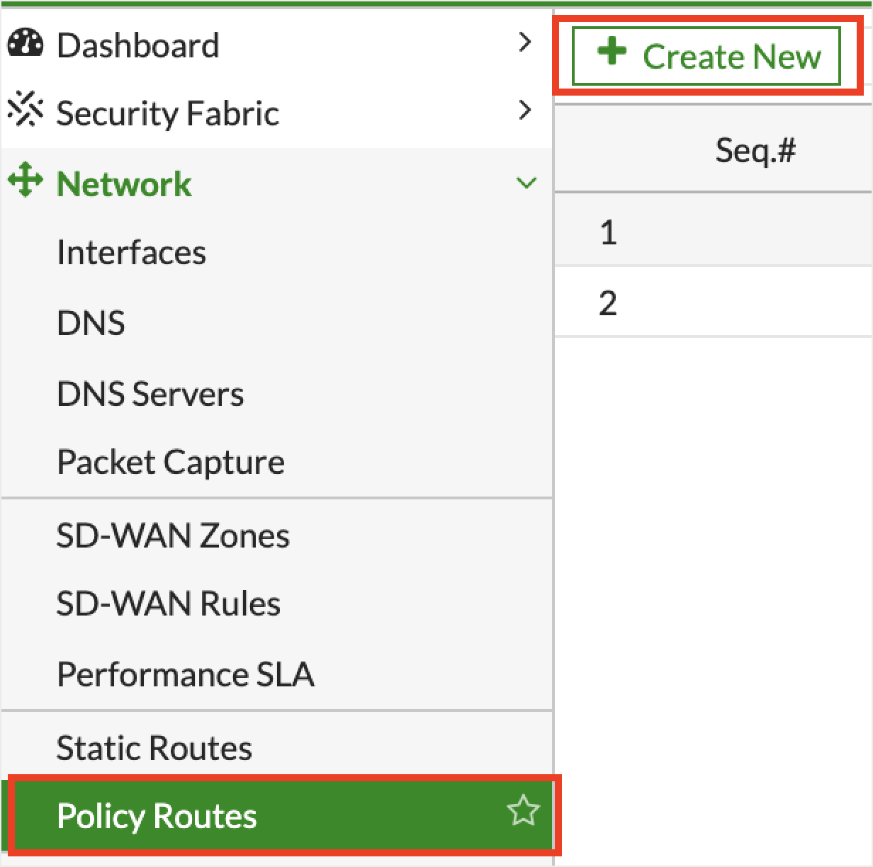
Go to Network > Policy Routes.
Click + Create New.
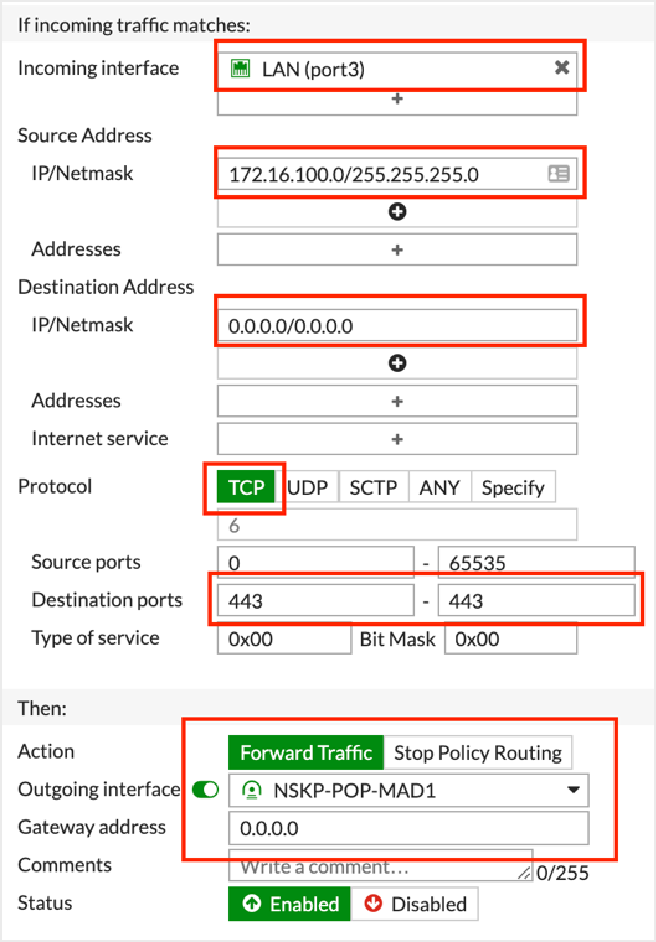
Create at least two PBRs (one for HTTP and another for HTTPS).
To create the IPSec tunnels for FortiGate in the Netskope UI:
Go to Settings > Security Cloud Platform > IPSec.
Click Add New Tunnel.
In the Add New IPSec Tunnel window:
Tunnel Name: Enter a name for the IPSec tunnel.
Source IP Address: (Optional) Enter the source peer IP address (i.e., exit public IP) of the FortiGate firewall that Netskope will receive packets from. Netskope identifies traffic belonging to your organization through your router or firewall IP addresses.
Source Identity: Enter an IP address, a fully-qualified domain name (FQDN), or an ID in email address format. For example, 1.1.1.1 or sourcelocation@company.com. The router or firewall uses the source identity for authentication during Internet Key Exchange (IKE).
Primary Netskope POP: Select the primary Netskope point of presence (POP) closest to you, and copy the IPSec Gateway IP address. You need this information to establish the primary IPSec tunnel on your FortiGate firewall. For optimal performance, Netskope recommends using the geographically closest POPs and configuring at least two tunnels for each egress location in your network.
Failover Netskope POP: Select the backup Netskope POP closest to you, and copy the IPSec Gateway IP address. You need this information to establish the backup IPSec tunnel on your FortiGate firewall. For optimal performance, Netskope recommends using the geographically closest POPs and configuring at least two tunnels for each egress location in your network.
Pre-Shared Key (PSK): Enter the pre-shared key that both sides of the tunnel will use to authenticate one another. The PSK must be unique for each tunnel.
Encryption Cipher: Select an encryption algorithm for the IPSec tunnel.
Maximum Bandwidth: Enter the maximum bandwidth for the IPSec tunnel. The tunnel size can be up to 1 Gbps. To enable the 1 Gbps option, contact your Sales Representative.
Advanced Settings: Click to view the following options.
Rekey: Select to rekey SAs when they expire. Netskope recommends using the default setting.
Reauthentication: Select to create new IKE and IPSec SAs when they expire. Netskope recommends using the default setting.
Trust X-Forwarded-For Header: Select to trust IP addresses contained in the X-Forwarded-For (XFF) HTTP header at the tunnel level. If you trust XFF at the tenant level, you can't select this option.
Apply to all traffic: Use the XFF HTTP header to identify all user traffic going through the IPSec tunnel.
Apply to specific NAT/proxy IP(s): Use the XFF HTTP header to identify traffic from specific NAT and proxy IP addresses going through the IPSec tunnel. Click +Add Another to add multiple IP addresses.
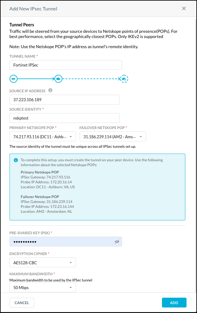
Click Add.
Following are some helpful commands for troubleshooting the configuration:
Enter the following command to enable debug for an IPSec connection:
diagnose debug application ike -1
diagnose debug enable
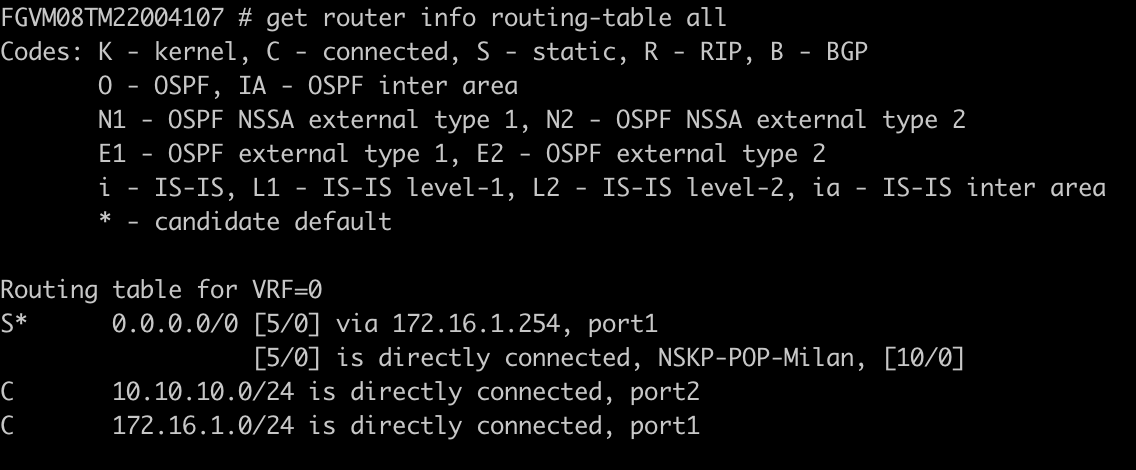
Enter the following command to obtain the whole routing table:
get router info routing-table all
Enter the following command to obtain an IPSec tunnel summary:
get vpn ipsec tunnel summary

Enter the following command to obtain the IPSec tunnel details:
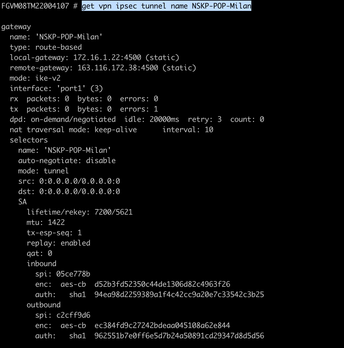
get vpn ipsec tunnel name NSKP-POP-XXXXXX
